http://www.talkingelectronics.com/te_interactive_index.html
|

Fig 71a Constant-Current Circuits
|
The three circuits to the right provide a constant current through the LED (or LEDs) when the supply rises to 15v and higher. The second and third circuits can be turned on and off via the input line.
|
|

Fig 71b Constant-Current Circuit
|
The first circuit in Fig 71b is a constant-current arrangement, providing a fixed current to the LEDs, no matter the supply voltage.
This is done by turning on the top transistor via the 2k2 resistor. It keeps turning on until the voltage-drop across resistor R is 0.65v. At this point the lower transistor starts to turn on and current flows through the collector-emitter terminals and it "robs" the top transistor of current from the 2k2 resistor. The top transistor cannot turn on any more and the current flowing though R is the same as the current flowing through the LEDs and does not increase.
The second diagram in Fig 71b is also a constant-current circuit with the base fixed at:
0.7v + 0.7v = 1.4v via the two diodes.
The transistor is turned on via the 2k2 resistor and a voltage is developed across resistor R. When this voltage is 0.7v, the emitter is 0.7v above the 0v rail and the base is 1.4v. If the transistor turns on more, the emitter will be 0.8v above the 0v rail and this will only give 0.6v between base and emitter. The transistor would not be turned on with this voltage-drop, so the transistor cannot be turned on any more than 0.65v across the resistor R.
|

Fig 71ba Constant-Current Circuit
|
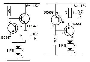
Fig 71ba shows two more constant current circuits "sourcing" the LEDs. The 7 constant current circuits give you the choice of either sourcing or sinking the LED current.
If the supply voltage is high, the transistor controlling the current (BC547) will get hot and alter the current-flow.
|

Fig 71bab Constant-Current
Circuit for high voltage supply
|
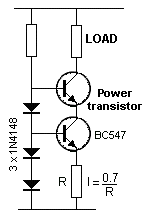
Fig 71bab uses a POWER TRANSISTOR to dissipate the losses and the current-controlling transistor remains cold.
When the circuit turns ON, the current through R is zero and the voltage on the base of the BC547 turns it on fully. The voltage between collector and emitter is about 0.2v and this means the emitter of the power transistor is below the base of the BC547. The base of the power transistor is 0.7v above the base of the BC547 and the power transistor also turns on fully.
Current increases through R and when the voltage across R reaches 0.7v, The BC547 starts to turn OFF. The collector voltage rises and this starts to turn OFF the power transistor. This is how the current through the LOAD is limited by the value of R.
The three circuits above provide a constant current through the LED (or LEDs) when the supply rises to 15v and higher. The second and third circuits can be turned on and off via the input line.
|
Relevant Pages
Pages in Other Languages
Regional
ReplaceWithDMOZlink: https://www.dmoz.org/
Subcategories
Categories
Comments (0)
You don't have permission to comment on this page.